Why Kaolinitic Clays Help Minimize Thermal Shock in Refractory Applications
In industrial practice, many linings fail not at peak temperature, but during heat‑up, shutdown, or process upsets. The governing mechanism is thermal shock: transient temperature gradients that generate tensile stresses exceeding the local fracture strength. Kaolinitic clays, when correctly processed and integrated into refractory formulations, contribute to a mullite‑bearing, low‑defect microstructure with improved thermal shock resistance (TSR) and reduced spalling propensity.
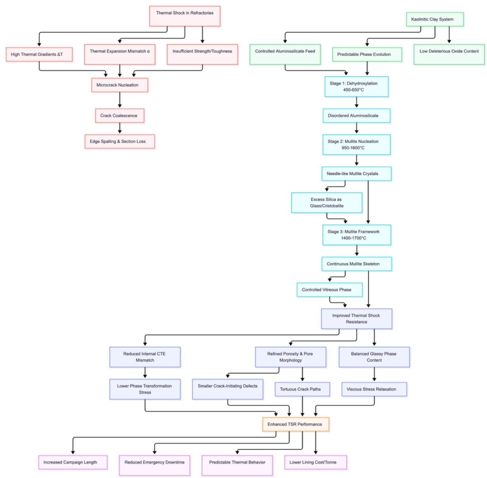
Thermal Shock in Refractories: A Stress–Microstructure Problem
Thermal shock in refractories is fundamentally a coupling of:
- High thermal gradients (ΔT) through the section
- Thermal expansion mismatch (α) between phases and across the microstructure
- Insufficient strength/toughness (σ_f, K_IC) relative to the induced stress field
Rapid heating or cooling produces differential expansion, particularly between hot face and cold face and between phases with different α. This leads to:
- Microcrack nucleation at stress concentrators (pores, sharp grain boundaries, weak interfaces)
- Crack coalescence into macrocracks
- Edge spalling and local section loss
Even a composition with high refractoriness under load (RUL) can perform poorly in TSR if the phase assemblage and pore architecture are not properly controlled.
Role of Kaolinitic Clay in the Refractory Mineral System
Kaolin is a kaolinite‑rich aluminosilicate with a suitable Al₂O₃–SiO₂ ratio for mullite generation and a relatively low content of deleterious fluxing oxides (Fe₂O₃, alkalis, TiO₂, CaO) in refractory‑grade selections. Its relevance to TSR arises from its behaviour under controlled calcination and mullitisation.
Key technical functions:
- Provides a controlled aluminosilicate feed for mullite formation.
- Enables a predictable dehydroxylation and phase evolution route.
- Contributes to a mullite‑dominated, low‑glass phase assemblage when correctly fired.
In short, kaolin is a design‑grade aluminosilicate rather than a generic clay.
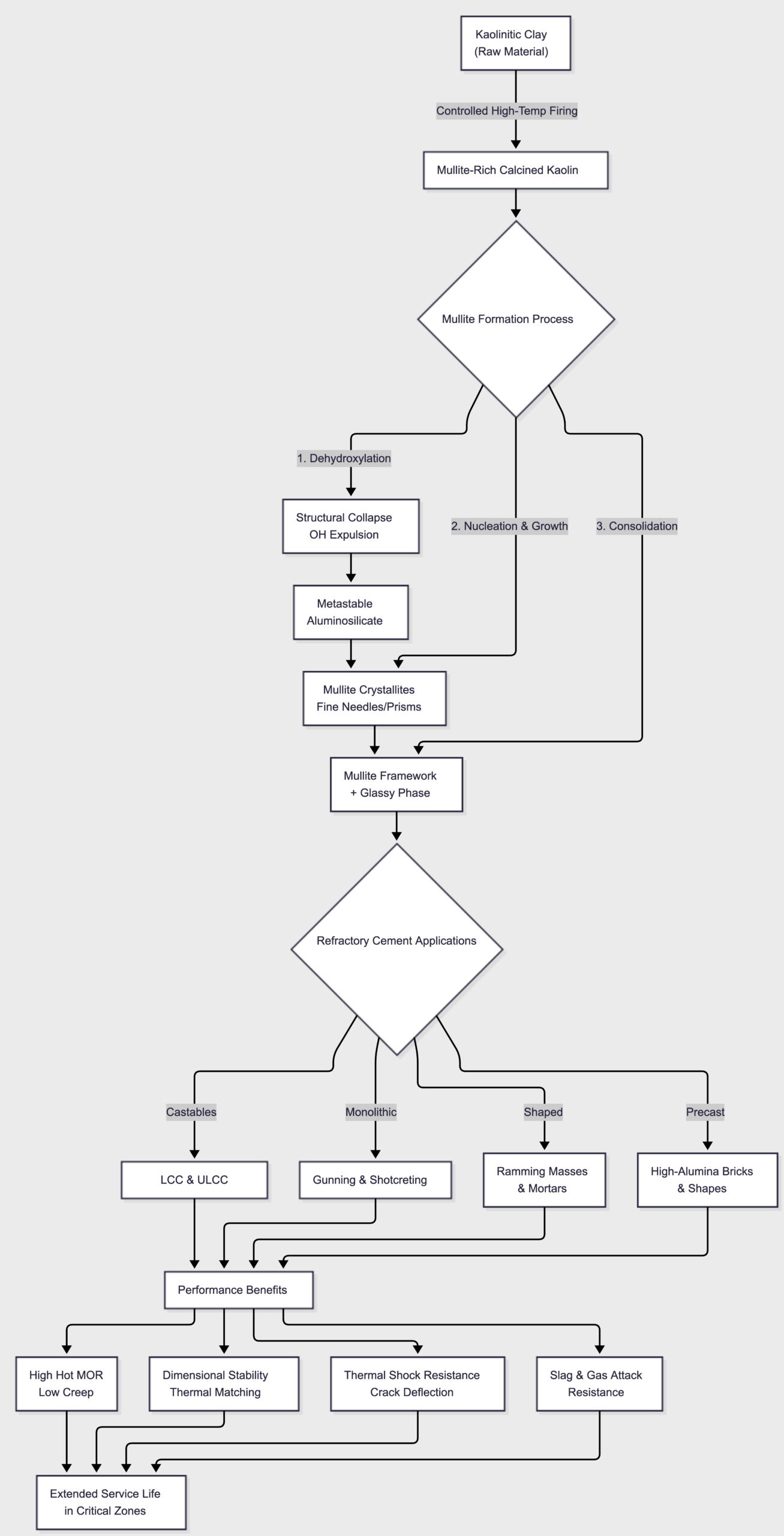
Phase Evolution: From Kaolinite to Mullite‑Bearing Microstructure
The transformation route under appropriate firing schedules can be summarised as:
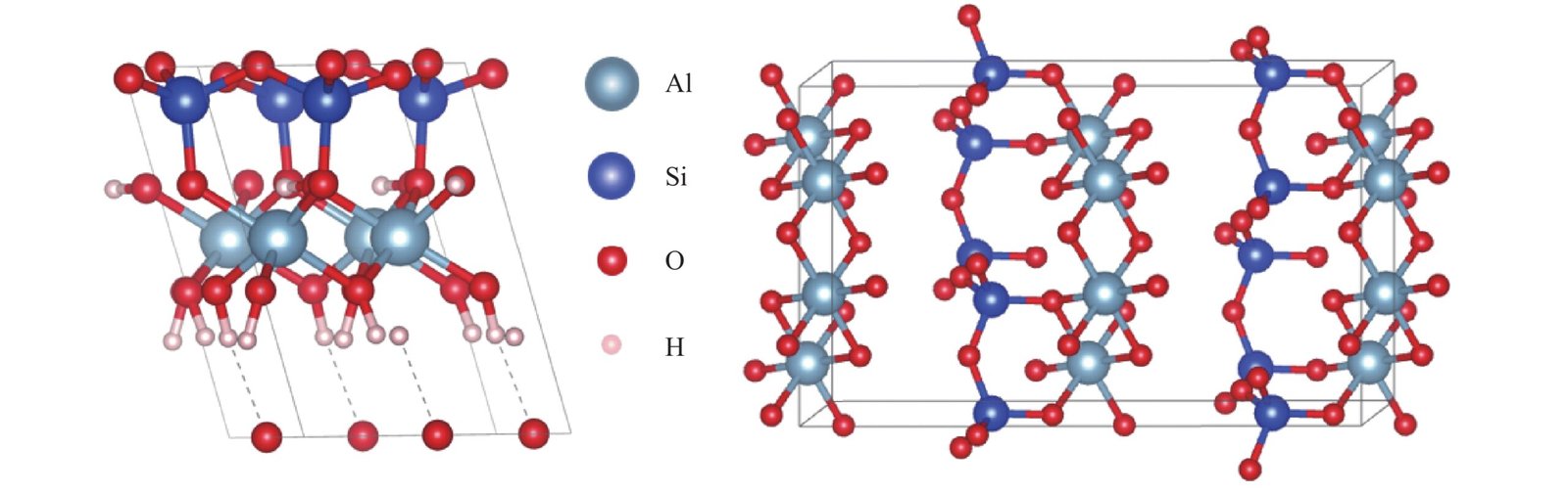
1. Dehydroxylation and structural collapse
Kaolinite → dehydroxylated aluminosilicate (metastable)
- Loss of structural OH
- Breakdown of the layered structure
- Formation of a disordered aluminosilicate phase suitable for mullite nucleation
2. Mullite nucleation and growth
At elevated temperature, Al‑rich regions reorganise to form mullite (3Al₂O₃·2SiO₂) crystallites:
- Needle/prismatic mullite crystals form within the matrix.
- Excess SiO₂ segregates as intergranular glass and/or cristobalite/quartz.
- Mullite crystal size, aspect ratio and volume fraction are governed by peak temperature, soak time and impurity profile.
3. Mullite‑rich framework and controlled vitreous phase
The target state is:
- Continuous or semi‑continuous mullite skeleton.
- Limited, well‑distributed vitreous phase to assist neck formation and controlled sintering.
- Minimal low‑melting eutectic phases that would degrade TSR and creep.
This pre‑engineered mullite content is central to the thermal shock response of the final refractory.
Transformation Route: From Kaolinite to Mullite-Rich Refractory
| Stage 1 | Stage 2 | Stage 3 |
| Dehydroxylation & Structural Collapse | Mullite Nucleation & Growth | Mullite-Rich Framework Formation |
| 450–650°C | 950–1600°C | 1400–1700°C (depending on composition) |
| Loss of structural OH; formation of disordered aluminosilicate suitable for mullite nucleation. | Needle-like mullite crystals form; excess silica segregates as glassy phase and/or cristobalite. | Continuous mullite skeleton with controlled vitreous phase, enhancing refractory performance and thermal shock resistance. |
Outcome: Pre-engineered mullite content leading to improved thermal shock resistance, higher-temperature stability, enhanced creep resistance, and longer refractory service life.
How Kaolin‑Derived Mullite Supports Thermal Shock Resistance
1. Phase composition and thermal expansion behaviour
Mullite has:
- High melting point and good high‑temperature strength.
- Moderate and relatively isotropic coefficient of thermal expansion (CTE).
By driving the system towards a mullite‑rich phase assemblage, kaolin‑based bodies exhibit:
- Reduced internal CTE mismatch between the matrix and mullite grains.
- Lower tendency for phase‑transformation‑induced volume jumps within the operating window.
This mitigates stress concentrations at phase boundaries during thermal cycling.
2. Microstructure: porosity, pore morphology and crack paths
Kaolin‑derived mullite fines can be used to tune the granulometry:
- Fines fill interstices between coarse chamotte/alumina/bauxite fractions.
- Open porosity and pore connectivity are refined; large, sharp‑edged pores are reduced.
- Pore size distribution shifts towards smaller radii, lowering crack‑initiating defect size.
Under thermal shock, crack paths encounter mullite grains and more tortuous intergranular networks, which helps blunt and deflect cracks, effectively increasing the fracture energy required for spalling.
3. Balanced glassy phase content
Complete elimination of glassy phase is rarely optimal for TSR. Kaolin‑based systems, if correctly fired, provide:
- A modest glassy phase to promote viscous stress relaxation and microcrack “healing” to some extent.
- Avoidance of excessive glass that would increase CTE mismatch and promote creep and softening.
This balance is important: a microstructure that is too rigid and brittle or too glassy can both perform poorly under thermal shock.
Practical Thermal Shock Scenarios Where Kaolin Helps
Kaolin‑containing, mullite‑forming systems are particularly relevant in:
- Cyclic furnaces and kilns with frequent heat‑up/shutdown.
- Burner and flame‑impingement zones, where steep surface temperature gradients occur.
- Load‑bearing monolithic in boilers and cement preheaters exposed to fluctuating gas temperatures.
- Repair gunning mixes and ramming masses expected to see differential expansion between old and new lining.
In these cases, improved TSR manifests as:
- Slower propagation of microcracks.
- Reduced edge chipping and spall depth.
- Longer intervals between hot‑spot development and full section failure.
Commercial and Operational Implications
From an expert’s standpoint, TSR improvement via kaolin‑derived mullite phases and tuned microstructure translates into:
- Increased campaign length before major relining.
- Reduced emergency downtime due to thermal shock‑induced spalling.
- More predictable behaviour during initial heat‑up and subsequent cycles.
- Lower lining cost per tonne of production over the asset life.
The value is not abstract: fewer unplanned breakouts and less frequent localised repairs.
PRPL’s View on Kaolin in Refractory Design
At Patel Nagar Refractories Pvt. Ltd. (PRPL), kaolinitic clays are treated as controlled aluminosilicate feedstocks for mullite‑bearing systems, not commodity fillers. The focus is on:
- Tight control of mineralogy and impurity profile (Al₂O₃/SiO₂ ratio, Fe₂O₃, alkalis, TiO₂).
- Calcination schedules that drive appropriate mullite formation and pore evolution.
- Integration into high‑alumina and aluminosilicate castables, mortars and ramming masses where TSR is a design criterion.
If you are benchmarking or re‑optimising TSR in castables, monolithic or shapes, kaolin‑based mullite development is one lever worth quantifying alongside aggregate selection, fibre additions and binder chemistry.